Page 148 - Catalogue Capteurs
P. 148

Schémas                                Solutions de détection de sécurité
                                                     Systèmes magnétiques codés


            Schémas
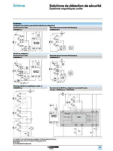
            Catégorie 3 (ce schéma peut atteindre SIL2/PL=d, catégorie 3)                                           1 1
            Raccordement par câble                   Raccordement par connecteur M12 (Coding A)
            XCSDM3791pp                              XCSDM3791M12
                                                                  F1
                                     N   L                           +
              BN +                     F1              1          2 A
                    I1 GY              2 A                  I1 7  +
                                                                                                                    2 2
                                 GND  N  L
                   O1 BK                                    O1 4
                    I2 PK          Alimentation             I2 6  +
                                   ABL 8pppp
                   O2 WH                                    O2 2  K2  K1
                         K2   K1                                           6  4
                                 GND  0V  24V                             7    3
                      BU
                         (1)                                  3  (1)   –   1  2                                     3 3
                      –
            SIL3/PL=e, catégorie 4
            Raccordement par câble                   Raccordement par connecteur M12 (Coding A)
            XCSDM4801pp                              XCSDM4801M12
                                                                  F1
                                     N  L
                                                       1             +                                              4 4
              BN +                    F1               Diag  +    2 A Vers
                   +                  2 A
              Diag                                                 PLC
                                                            Er  7
                   Er  VT  Vers  GND  N  L                  I1 5  +
                   I1 GY  + PLC
                                                            O1 4
                                  Alimentation                    +         5
                   O1 BK                                    I2 6          6   4
                                   ABL 8pppp
                   I2 PK  +
                                                            O2 2         7     3
                                                                  K2  K1                                            5 5 5
                   O2 WH                                                  1   2
                         K2  K1  GND  0V  24V                               8
                     BU
                                                          Start  3  (1) (4)  –
                Start  –  (1)(4)                       8  input      +
             OG  input      +                                K2  K1
                    K2  K1
            Chaînage systèmes magnétiques codés (2)                                                                 6 6
            XCSDM3791pp                              Raccordement de SIL3/PL=e, catégorie 4 avec module Preventa
                              F1  +                  Exemple : XCSDM3ppppp + XPSAFL5130
                              2 A
                   I1    +                                         F1
                                                                   2 A
                  O1
                                                                               I1
                   I2    +                                                                                          7 7
                                                                               O1
                  O2
                                                                               I2
                        –
                  +
                                                        N   L                  O2
                   I1
                                                          F2
                                                          (3)
                  O1                                                                                                8 8
                                                                   A1                               13  23
                   I2                                GND  N  L
                                                                     XPS Apppp
                                                      Alimentation
                  O2
                                                       ABL 8pppp                    Logique    K1
                       –                                                  T
                  +
                                                                                               K2
                                                                                                                    9 9
                   I1                                GND 0V   24V
                  O1                                               A2            S33    S34         14  24
                   I2
                             K1                                                 K1                     K1
                  O2
                                                                                     S3
                                                                                 K2               K2
                         K2
                                                                                                                   10
                                                                                                                   10
                            (1)    –
            (1) Les bobines K1 et K2 doivent être protégées à l’aide de suppresseurs d’arc.
            (2) Chaînage maxi : 32 avec un câble d’une longueur de 2 m.
            (3) 2 A maxi.
            (4) Contacts liés mécaniquement.
                                                                                                            87
   143   144   145   146   147   148   149   150   151   152   153